

Understanding the Basics of PCB Design
The Role of PCB in Electronics
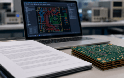
At the heart of every electronic gadget that makes our life easier, from the smartphone in your pocket to the microwave that heats your meals, lies a printed circuit board (PCB). It’s like the central nervous system of electronics, connecting various components through a maze of pathways. But, what exactly goes into designing this crucial piece? Understanding the basics of PCB design is the first step for any aspiring electronics engineer looking to speed up their design process without cutting corners.
Key Components of PCB Design
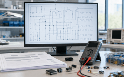
Diving into PCB design, we’re talking about more than just arranging components on a board. It’s an art form that requires a keen understanding of electrical functionality and physical layout. Key components include the board itself, which can vary in material and size, the traces (those copper pathways I mentioned), vias (think of these as elevators for electrical signals), and of course, the electronic components (resistors, capacitors, and the like). Each piece plays a vital role, and mastering how they all fit together is crucial for efficient PCB design.
Planning Your PCB Layout for Speed
Utilising Software Tools Efficiently
Gone are the days of manual drafting. Today’s PCB design is all about software that can think a step ahead of you. But, it’s not just about having the tools; it’s about wielding them like a pro. From schematic capture to layout and routing, using software efficiently can slash your design time. It’s like being handed a map in a maze – suddenly, you know exactly where to go.
Importance of Component Placement
Let’s talk about real estate for a moment – in the world of PCB design, placement is everything. It’s not just about fitting everything onto the board; it’s about strategic positioning that optimises performance and reduces interference. Think of it as organising a party where everyone needs to chat without shouting across the room. Getting component placement right from the get-go can save you a headache later on.
Streamlining the Design Process with Prototyping
Rapid Prototyping Techniques
In the realm of PCB design, the mantra ‘fail fast, fail cheap’ couldn’t be more apt. Rapid prototyping allows you to test the waters without diving in headfirst. Whether it’s 3D printing your PCB for a quick physical review or using software simulations to test functionality, these techniques can provide invaluable insights early on. It’s like taking a test drive before buying the car – why wouldn’t you?
Testing and Iteration for Improvement
Iteration is the key to perfection. Each prototype offers a learning opportunity, a chance to tweak and refine. Think of it as honing a diamond – every cut brings you closer to the ideal shape. By embracing a cycle of testing and iteration, you can significantly enhance the quality and functionality of your PCB designs. It’s a journey of continuous improvement, where each step forward is guided by the lessons learned from the last.
Leveraging Advanced PCB Design Software Features
Automation Tools to Save Time
In the high-speed world of PCB design, automation is your best friend. Imagine having a personal assistant that takes care of the tedious tasks, allowing you to focus on the creative aspects. Advanced PCB design software comes packed with automation tools that can do just that. From auto-routing to component placement optimisation, these features can drastically reduce design time. It’s like setting up a row of dominoes and watching them fall perfectly into place with just a flick.
Error Detection and Correction Features
Mistakes happen to the best of us, but in PCB design, they can be costly and time-consuming to fix. That’s where error detection and correction features come into play. It’s like having a safety net that catches you before you fall. These software tools scan your design for common errors, such as short circuits or incorrect component spacing, ensuring that your board is not only designed quickly but also accurately. Think of it as having an eagle-eyed friend who spots the typos in your important email before you hit send.
Tips for Efficient Schematic Capture
Organising Schematics Logically
Schematic capture is like sketching the blueprint of your PCB design. It lays the groundwork for everything that follows. But a cluttered schematic is like a map without clear directions – confusing and unhelpful. By organising schematics logically, grouping related components together, and using clear labeling, you transform this map into an easy-to-navigate guide. It’s about making the complex simple, ensuring that anyone who follows your schematic can clearly see the path you’ve laid out.
Harnessing the Power of Libraries
Why reinvent the wheel every time you need a component in your design? Libraries in PCB design software are treasure troves of pre-designed components, waiting to be utilised. It’s akin to having a toolkit at your disposal, where every tool has been prepped and primed for use. By harnessing the power of libraries, you not only speed up the design process but also ensure consistency and accuracy in your work. It’s like cooking with the best ingredients at hand – the outcome is always better.
Optimising PCB Design for Manufacturing
Design for Manufacturability (DFM) Guidelines
Designing with manufacturing in mind is like building a bridge with the final destination in sight. DFM guidelines are there to ensure that your PCB design is as smooth to manufacture as it is functional. This involves considering factors like material choice, board thickness, and trace widths right from the start. By adhering to these guidelines, you’re not just designing; you’re designing with purpose. It’s a proactive approach that minimizes the need for costly revisions and ensures a seamless transition from design to production.
Communicating Effectively with Manufacturers
Clear communication with your manufacturer is the linchpin of a successful PCB project. Think of your manufacturer as a partner in your design journey, one who can offer valuable insights and suggestions. By keeping the lines of communication open, you can anticipate and address potential issues before they become problems. It’s like dancing in sync – when both partners are in tune, the performance is seamless.
In the evolving world of PCB design, blending foundational knowledge with advanced tools shapes a process that balances speed and precision. For electronics engineers, this means leveraging software, engaging in prototyping, and ensuring manufacturability to craft designs that go beyond basic connections, aiming for innovation and efficiency. As you navigate this journey, remember the importance of continuous improvement and collaboration with manufacturing partners. This guide serves as a beacon, urging a move towards smarter, more sustainable practices in PCB design, inviting you to push boundaries and innovate with every circuit you create.
")

0 Comments